Symmetry Boundary Conditions
With CENOS it is possible to simulate a symmetrical part of an object (half, quarter, slice, etc.), which gives valid results that can be mirrored to represent the whole geometry, but in the same time significantly decreases the calculation time.
To take into account the symmetry of the object and set up the simulation properly, symmetry boundary conditions (BC) are used, through which the position of magnetic field lines in respect to symmetry planes are defined.
Symmetry planes are defined as parallel or normal in respect to the magnetic field created by the inductor - if the inductor is unconventionally placed, the definitions of these planes may change.
Symmetry conditions should be defined for every domain in the simulation, e.g. not only for the workpiece slice, but for the air and flux concentrator domains as well!
Symmetry boundary conditions
When a current is flowing through a wire, it creates a magnetic field around it, with magnetic field moving around the current flow direction.
In induction heating when complex inductors are used and an object is placed within this magnetic field, some faces of the object are parallel to the magnetic field lines, while other are normal to them.
By knowing how the magnetic field lines are positioned, we can understand their position in respect to different surfaces or boundaries of our geometry.
Based on this fact, two symmetry boundary conditions are introduced - Flux Parallel and Flux Normal.
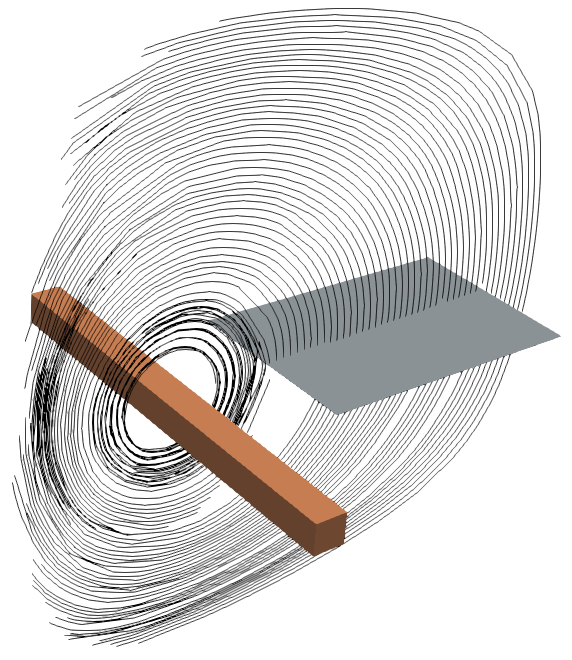
Flux parallel
Flux parallel BC defines that the magnetic field lines are parallel to the surface, meaning that these lines do not cross the plane.
In this example a straight inductor is generating a magnetic field, which lines are positioned parallel to a plane and are going along the side of it.
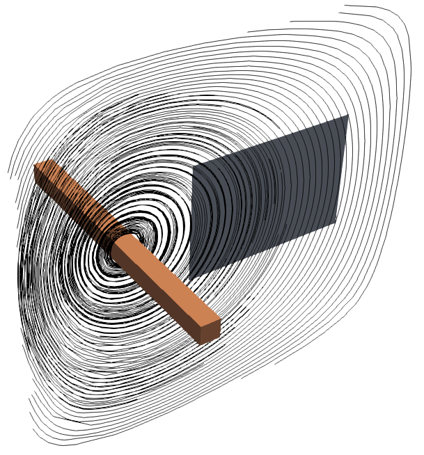
Flux normal
Flux normal BC defines that the magnetic field lines are normal to the surface, meaning that they go directly through the plane.
In this example a straight inductor is generating a magnetic field, which lines are positioned normal to a plane and are going straight through it.
Use of Symmetry BC
Symmetry BC are used to simulate only a small part of the whole geometry, significantly decreasing the calculation time while producing the same accurate results as full geometry cases.
In the next examples we will demonstrate the outer boundary definitions for different symmetry cases.
The only difference in physics setup for symmetry cases are the additional boundary conditions on the symmetry planes - the rest remains the same!
Half
Most of the induction heating systems are at some level symmetrical and can be sliced in half while preserving the accuracy of the results.
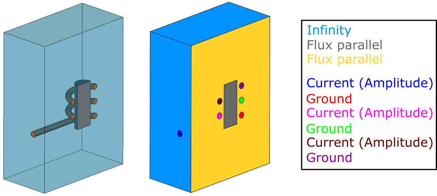
In this example we will look at a simple multiwinding coil and a cylindrical billet system. For full system on the outer boundaries we define Current (Amplitude) and Ground on the terminals, and the outer air faces with Infinity.
:::Important Notice how the same boundary condition (Flux parallel) is differently colored on differend domain surfaces - you need to define symmetry BC's separately for each domain! :::
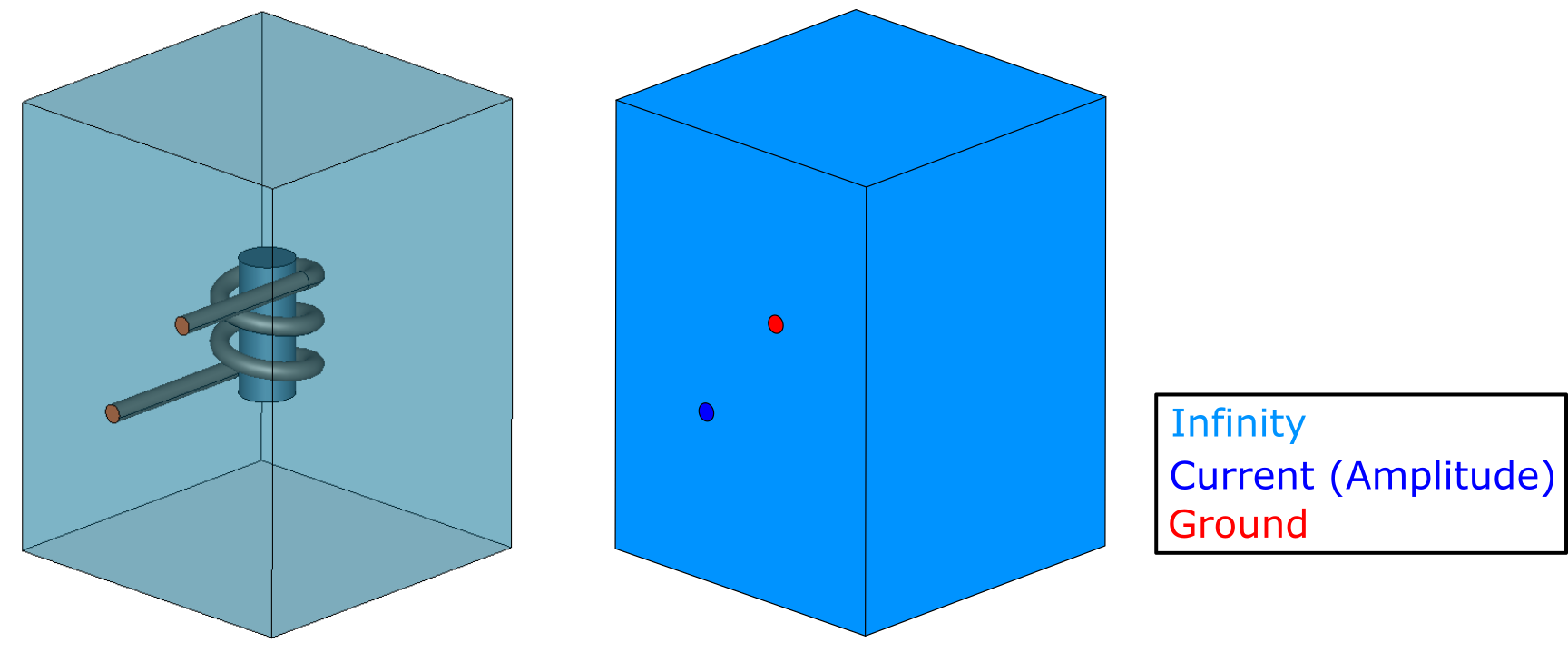
If we cut the geometry in half, we need additional boundary conditions to define the symmetry cut. We need to define the new symmetry planes for air and workpiece with Flux parallel, and for each half of the winding we need to create new terminals, on which we will define Current (Amplitude) and Ground.
Symmetry boundary condition for this case is Flux parallel, because the inductor parts which go into the plane creates a magnetic field parallel to these planes.
Quarter
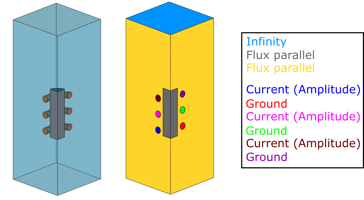
You can use the symmetry of your geometry even more and simulate not half, but a quarter of your system.
We will use the same geometry as we did for the half symmetry example, but this time we will set up only quarter of it.
The boundary conditions used are exactly the same as for half symmetry - define the symmetry planes for air and workpiece with Flux parallel, and for each quarter of the winding we need to create new terminals, on which we will define Current (Amplitude) and Ground.
Symmetry boundary condition on both symmetry planes are Flux parallel, because the inductor quarters which go into the plane creates a magnetic field parallel to both symmetry planes.
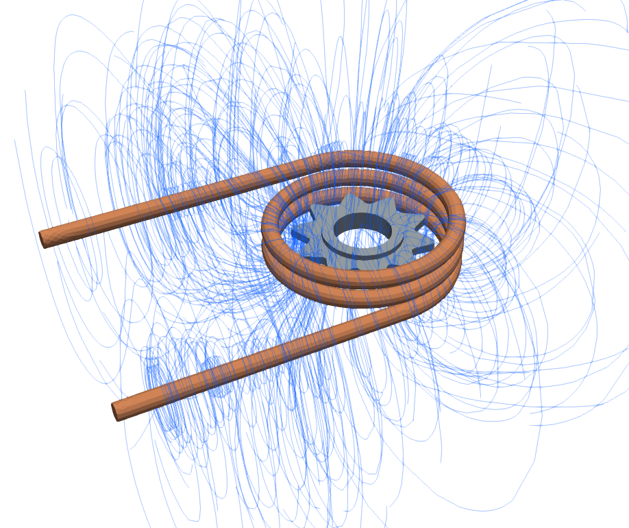
Slice
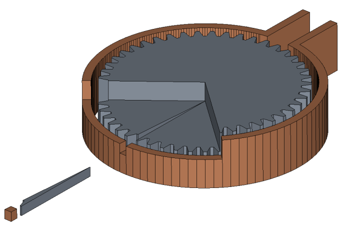
For geometries with some level of axial symmetry you can simulate only a slice.
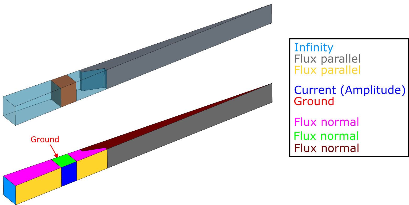
In the example below a half slice of the gear tooth has been cut out, and symmetry conditions need to be used not only for parallel, but for normal symmetry as well (notice that the slice is only a part of the full system height).
Parallel symmetry BC's are exactly the same as in the previous examples - define the symmetry planes for air and workpiece with Flux parallel, and for inductor slice create terminals, on which to define Current (Amplitude) and Ground.
We also need to define the normal symmetry (part of the full height of the system), which is why for inductor, air and workpiece top and bottom faces Flux normal is defined.
If the inductor is sliced and only a part of the full height is simulated, the current value should be decreased respectively, e.g. if only half of the full conductor height is simulated, the current should be decreased by half.
Limitations
Symmetry usage for case optimization is very useful, but there are some things to keep in mind when creating simulations with symmetry.
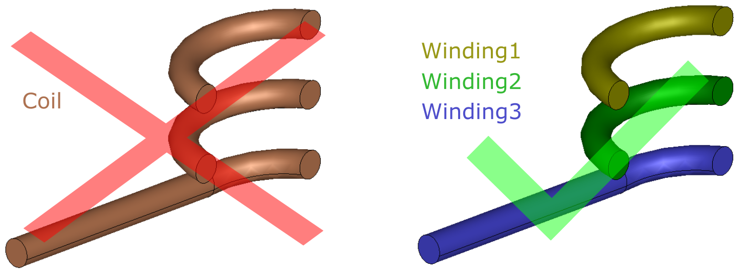
Separate windings
For simulations with full geometries you have one inductor volume, for which you define two terminals. If you are slicing this inductor in half or in smaller parts to use symmetry, remember that you need to define each inductor volume (windings) separately and create two terminals and set current on each of them.
For voltage control input, if you have the full applied voltage value ( let's say 1000v ) and have sliced the inductor into 5x loops, then the voltage in each of these loops will be full voltage / number of loops
exmple= 1000 / 5 = 200 volts.
You have to apply also the slice angle to this equation.
For example we have a 180 degree slice, 180 degree slice means we have to divide this voltage-per-loop by 2. Meaning 200 / 2 = 100 volts as the input for each loop. In physics, also input the "Slice" angle of 180 degrees, this will mainly make sure the power calculated should be as expected. :::
Rotation
If you want to simulate rotation using Complex Motion, Symmetry Boundary Conditions cannot be applied and you will need to calculate a case with full geometry.
for training review our webinar: https://www.youtube.com/watch?v=YKKJyNz-OPg