Meshing in Salome
mesh-overview or numerical grid creation is one of the most important parts of the simulation setup. Your results depend directly from the quality of the mesh, with coarse mesh being one of the biggest reasons for incorrect or even unphysical results.
CENOS has an integrated mesh builder, where the user can Select the size, density, gradient of the mesh, as well as modify the automatic values and refine specific edges or faces, nevertheless if the user requieres to create their own mesh from the third party tool Salome, it is still doable from our interface.
In this article we will go over the mesh creation in Salome, one of the open-source tools used by CENOS. You will learn how to interact with mesh setup window and go over different aspects and approaches used in mesh creation.
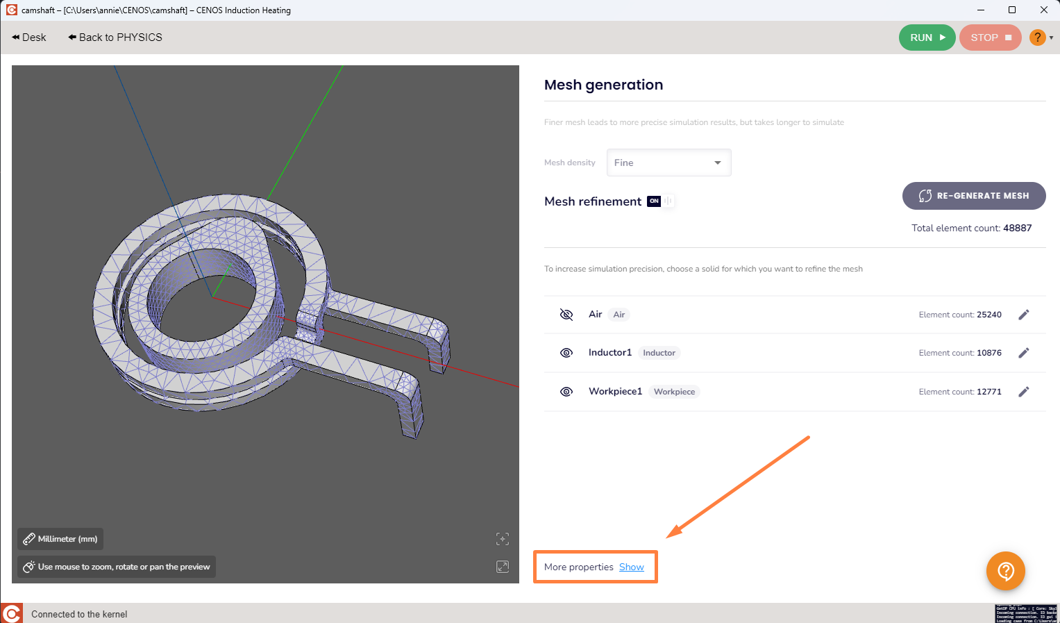
Once you have finished setting up both the geoemtry and the physics go to the mesh module, in the mesh module click on the show more button
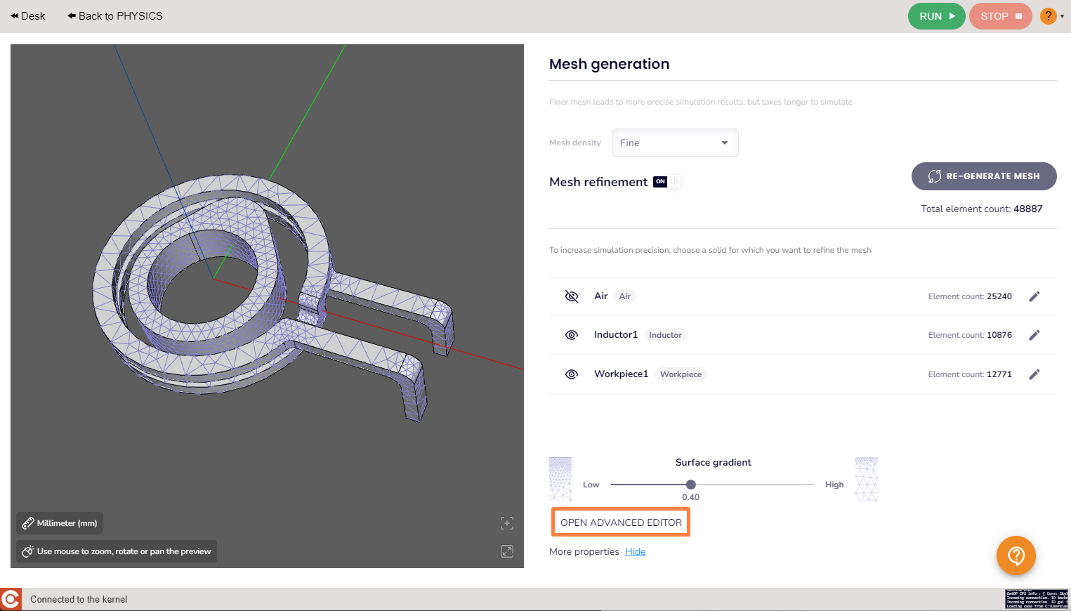
then click on the OPEN ADVANCED EDITOR button, a Salome instance and a python shell will pop up, don't close the pyton shell, and work inside Salome.
Now let's can dive into mesh creation. Before doing that switch from the geometry module to the mesh-overview module.
To create a mesh:
- Select the partition from which you want to create your mesh under Geometry (
 )
)

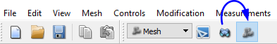
- Click Create Mesh (
 ) icon or choose it from dropdown menu under Mesh → Create Mesh.
Meshing interface
Now the mesh setup interface will be opened. The mesh window in Salome has four tabs - 3D, 2D, 1D and 0D. Each dimension (volumes – surfaces – edges) has its own meshing algorithm with its own parameters.
NOTE: You can also set meshing parameters for 0D elements (points), but this is rarely used.
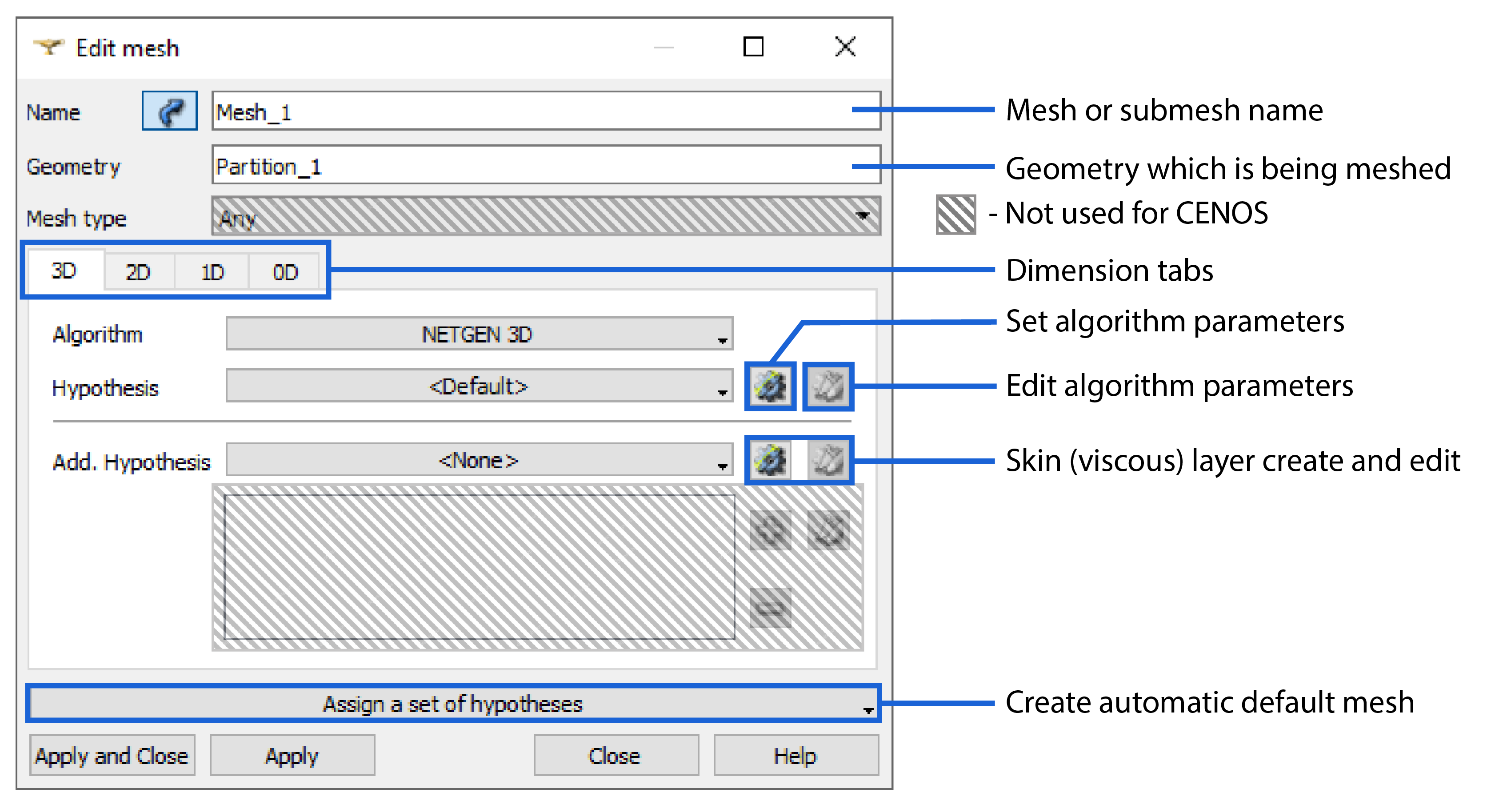
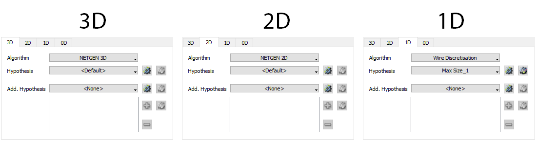
CENOS' engineers always start with the automatic mesh, it applies default algorithms for all dimensions and only needs the max element size definition, which is actually an element edge size. In automatic mesh 1D algorithm determines the size of the mesh, as the 2D and 3D algorithms are based off the 1D edges.
You can create an automatic mesh by clicking Assign a set of hypotheses → Automatic Tetrahedralization. For the air (main mesh) domain the default Max Lenght value is usually sufficient.

IMPORTANT: Max Lenght (mesh size) can later be changed in the 1D tab by clicking Edit algorithm parameters (![]() ).
).
To see how the mesh looks like hit calculate the mesh. To do that left click on the created mesh (![]() ) and click Compute (
) and click Compute (![]() ). While searching for the right mesh parameters we suggest using the Clear mesh data (left click on the mesh) function before computing again.
). While searching for the right mesh parameters we suggest using the Clear mesh data (left click on the mesh) function before computing again.
IMPORTANT: When calculating the mesh, if any sub-meshes are present, they will be calculated first, and only then the mesh definition from Mesh_1 will be applied to the rest of the geometry.
Sub-meshes
Sub-mesh is the same as previously mentioned mesh in terms of definition, just applied to a smaller domain. They are needed to increase the resolution of the mesh locally for domains such as workpiece and inductor, where smaller mesh elements are needed, while leaving mesh elements larger in other domains (such as air domain) where such high resolution it's not needed.
Sub-mesh can take many shapes – usually it is used for the workpiece and inductor resolution, but it is also possible to create a sub-mesh for certain parts of you workpiece or inductor, such as surfaces and edges, for even greater resolution.
Sub-mesh on solid
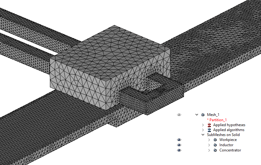
To create a sub-mesh you need to right-click your main mesh (Mesh_1), and click Create Sub-mesh (![]() ).
).
From partition dropdown in Object Browser select the geometry group for which you want to create a sub-mesh and create an automatic mesh as mentioned previously. Sub-mesh will appear under SubMeshes on Solid.
The default "automatic" mesh size will most likely be too large, so we suggest going 3-5 times smaller in the first size iteration.
Note that because we usually create a sub-mesh for every domain except air, the main mesh (Mesh_1) is responsible only for the air. Because of this the main mesh is usually made quite coarse.
Sub-mesh on surface
In some cases even greater local resolution of the mesh is needed. For this you can use and create a sub-mesh on one or more surfaces.
From partition dropdown in Object Browser select the geometry group for which you want to create a sub-mesh and create an automatic mesh as mentioned previously. Sub-mesh will appear under SubMeshes on Face.
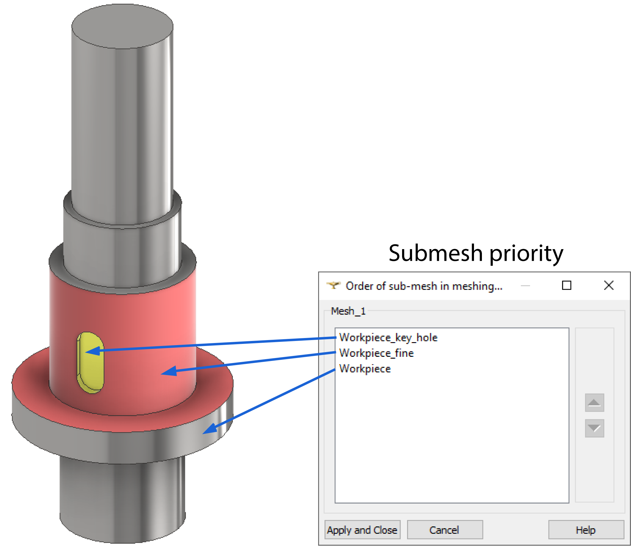
When creating multiple sub-meshes which overlap each other (for example, solid sub-mesh for the inductor and a surface sub-mesh for one part of the same inductor surface), a Submesh priority window will appear.
In the sub-mesh window you define the order the overlaping sub-meshes will be calculated. It is important because sub-mesh with lower priority will be partially based on the sub-mesh with a higher priority - because of this prioritize sub-meshes for which the quality of the mesh is more important.
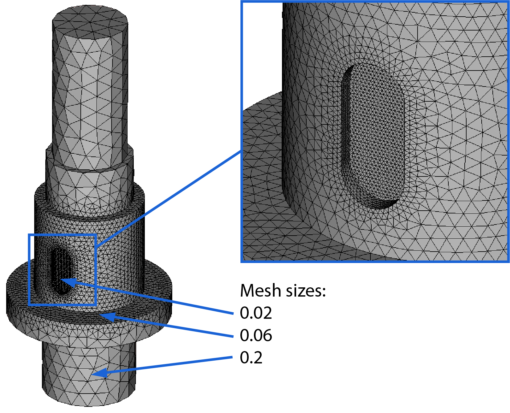
In this example sub-meshes are used on the shaft surface to create finer mesh near the key hole and on part of the shaft surface:
Sub-mesh can also be created for edges if you need additional refinement or if you are working with a 2D case.
2D Algorithms
If you use the automatic mesh option, it will use Mefisto algorithm for 2D surface definitions.
Mesfisto algorithm creates a mostly uniform mesh. Even though it is sufficient most of the time, sometimes it's needed a finer mesh element distribution near different sub-meshe borders. In that case you can change Mefisto algorithm to NETGEN 2D under 2D tab.
Here is an example of Mefisto vs. NETGEN 2D air mesh:
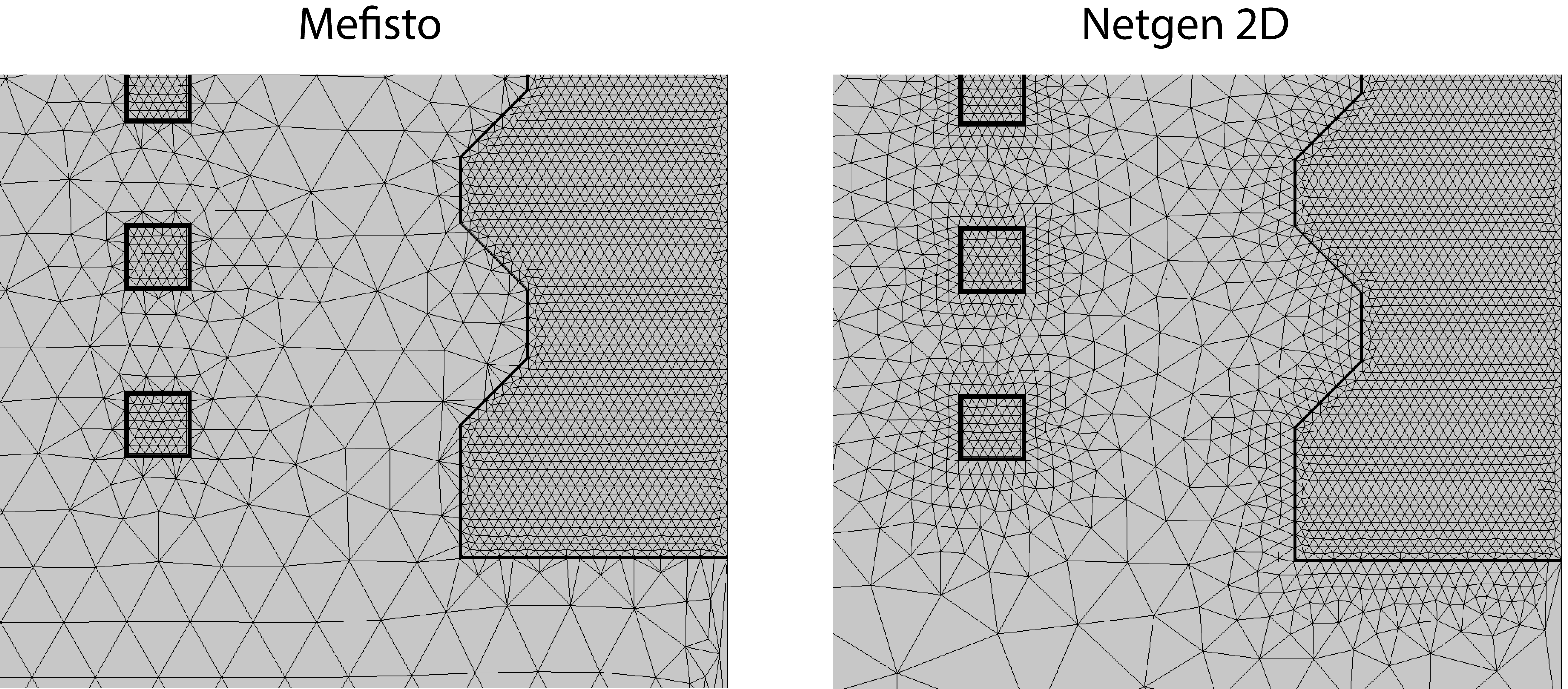
In our experience the NETGEN algorithm tends to be more resilient so we suggest using it for more complex geometries and air.
Skin layer
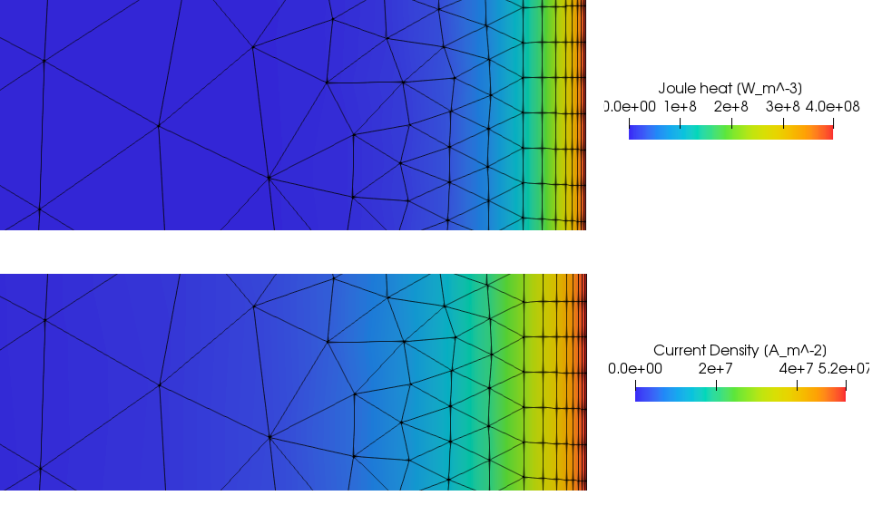
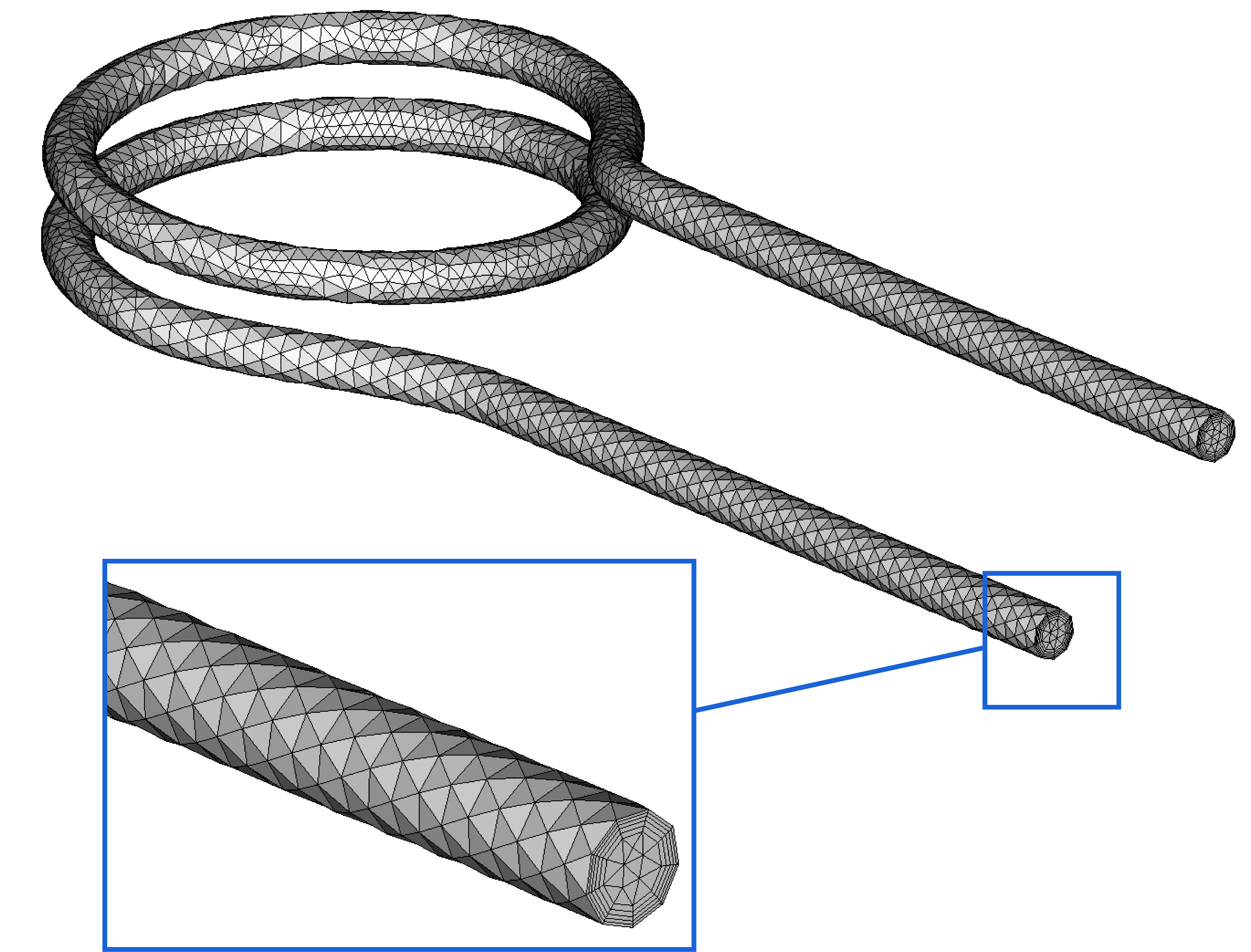
Both inductor and workpiece domains need a fine mesh layer on the surface to model the high density of currents near the surface it occurs due to the physical phenomenon known as skin effect. In Salome this can be easily resolved with Viscous Layers.
For induction heating simulations (usually in the workpiece) the Viscous Layers serves a dual purpose of both resolving surface currents and the heat conduction from the skin layer deeper into the workpiece.
Here you can see an example of Viscous Layers used to create a small layered elements on the surface of the workpiece to resolve current density:
Creating Viscous Layers
To create Viscous Layers in your sub-mesh window select 2D or 3D tab depending on the simulation type - 2D or 3D. Click the gear icon (![]() ) next to Add. Hypothesis and select Viscous Layers.
) next to Add. Hypothesis and select Viscous Layers.
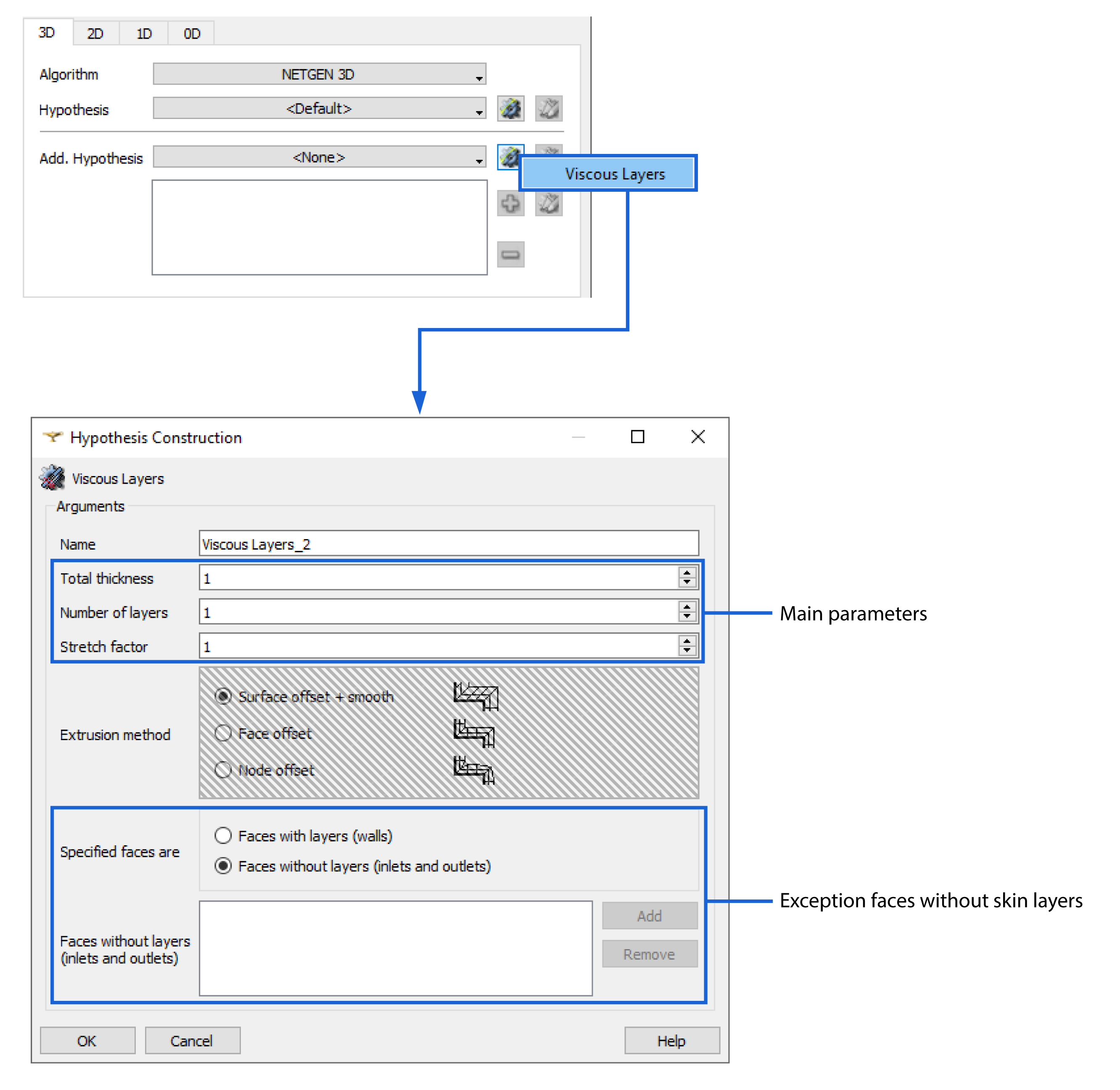
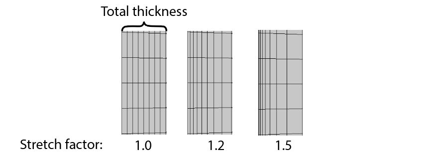
To define Viscous Layers, you need to enter 3 parameters - Total thickness, Number of layers and Stretch factor.
Total thickness - the total size of the skin layer, dependent from frequency and material properties;
Number of layers - defines how many layers you will create within the previously defined skin layer size;
Stretch factor - determines the gradient of the layer sizes - by how much the next layer will be larger that the previous one;
We suggest to start with the following parameters, where δ is skin effect depth for the respective domain:
| Workpiece | Inductor | |
|---|---|---|
| Total thickness | 1.5 δ | δ |
| Number of layers | ≈ 5 to 8 | ≈ 4 to 7 |
| Stretch factor | 1.5 | 1.4 |
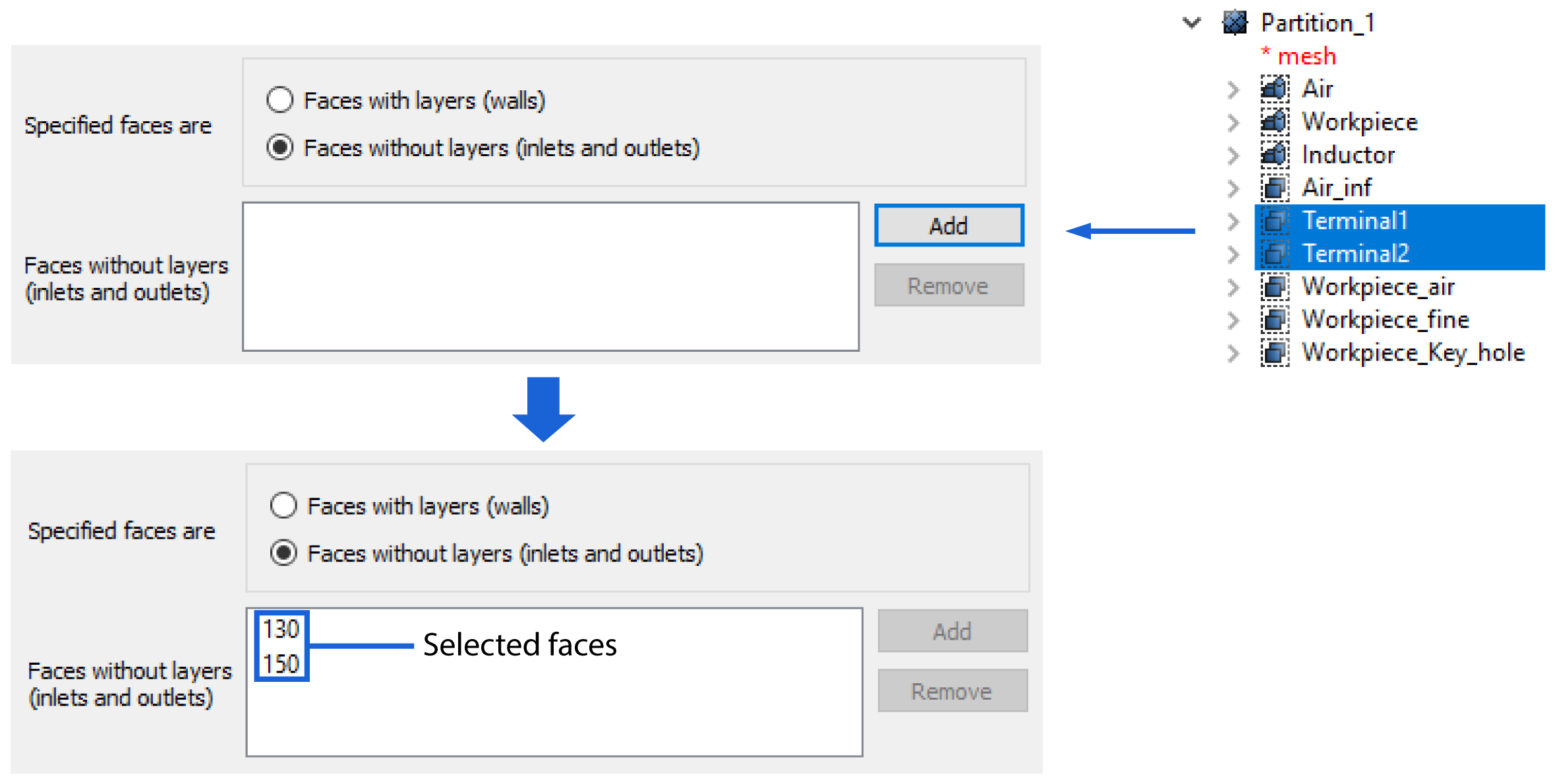
Faces without layers (inlets and outlets)
This feature allows us to exclude certain faces or edges from the skin layer, possibly decreasing element count significantly. This should be used for:
- Terminals of the inductor
- Inductor inside surface if the inductor has a cooling channel.
- Symmetry axis of a 2D workpiece.
- Any other workpiece parts that far away from the inductor.
To use this feature:
- Select the desired groups under your partition or select them directly from the Object window;
- Click Add;
- Verify the number of faces or edges in the selected faces window;
- Click OK and Apply and Close.
- Clear mesh data and recompute the submesh to see the changes.
Mesh size
We strongly recommend starting with a coarse mesh, so you have a shorter calculation time, just to see if everything is working correctly. Even with the absolute coarsest, the temperature and power estimation will be only about 6% off.
When you approximately have the results you were looking for, you can then decrease the mesh size to increase the accuracy of your results.
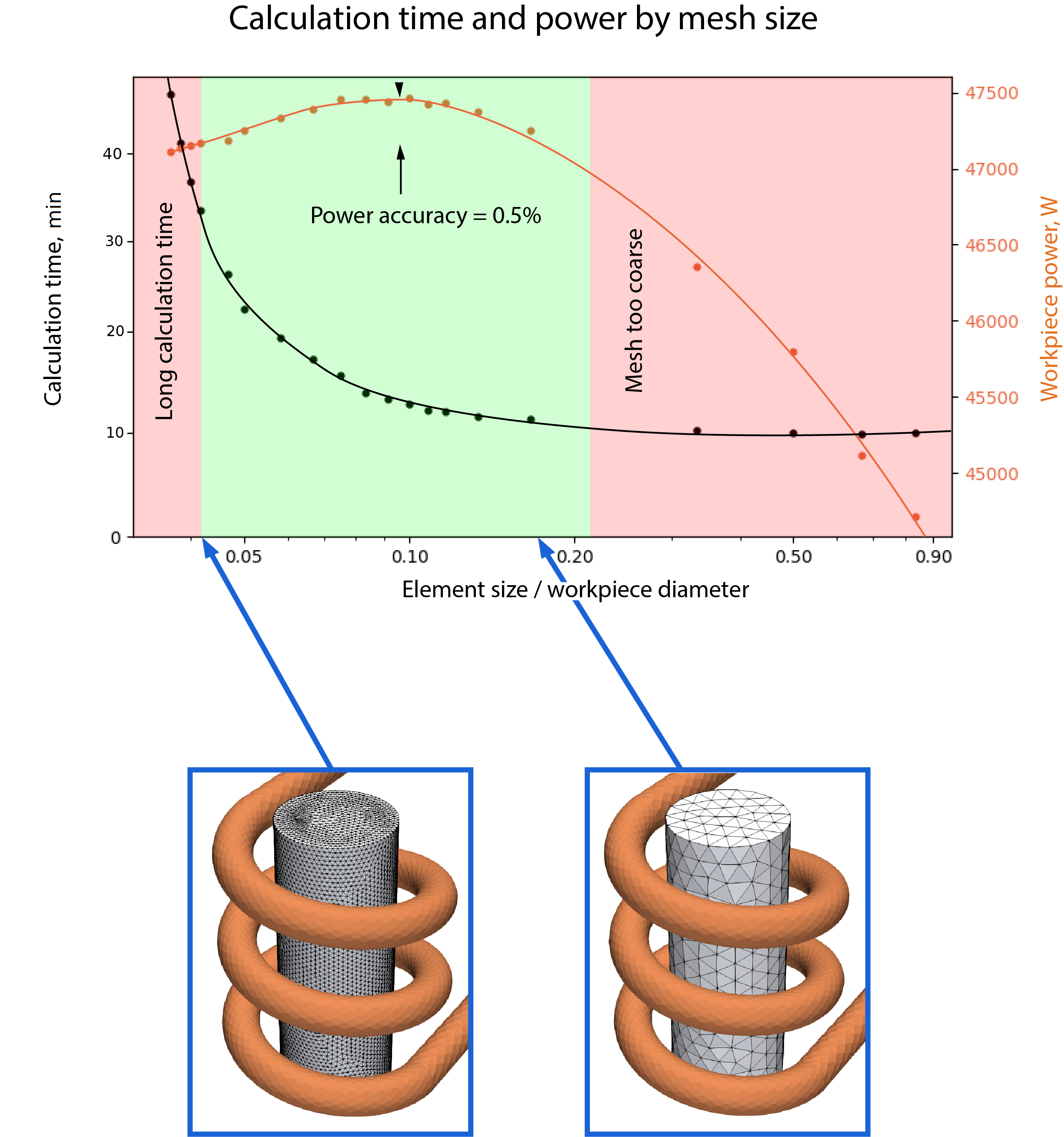
These results are just to demonstrate the effects and should not be used for reference, as your geometry shape will have a significant effect on your results. As you can see, the calculation time increases exponentially with the mesh size, so it is not worth pursuing the marginal gains with an overly fine mesh.