How to parameterize geometry
Induction heating simulations are a great tool to find the right parameters for the desired heating profile - from current and frequency values to inductor position relative to the workpiece.
In CENOS platform it is possible to create a parametric model and change the previously defined geometric values such as inductor position, winding size etc.
Without parametric values each geometry modification requires the creation of a new simulation model from the beginning, which can be time consuming. If the model is parametric, the modifications of the geometry require only the change of a parameter such as coil radius and export of the new mesh.
When to use parametric geometries?
Geometry parameterization is useful when searching for the right position between the workpiece and coil windings to achieve the optimal heating profile within the workpiece.
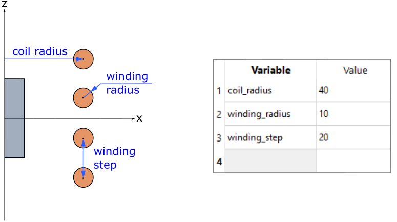
In the example below is shown a standard coil-workpiece configuration with 3 adjustable parameters - coil radius, winding radius and step between the windings.
How to create a parametric model?
First you need to decide which parameter you want to make parametric. Then you create a new parameter and implement it during the geometry building process.
In the next steps we will learn how to create a 2D geometrical model with adjustable coil winding diameter size.
1. Create a new variable parameter
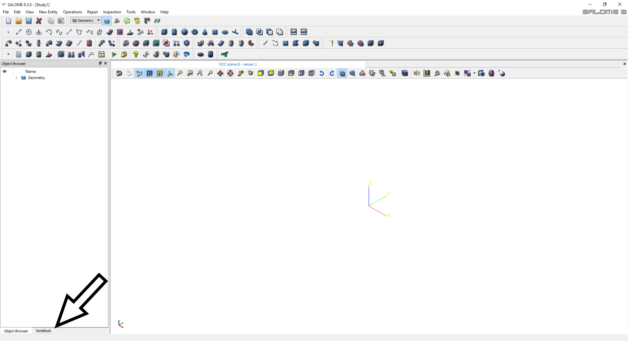
Variables in Salome are defined through NoteBook, which can be accessed by clicking on the NoteBook button under Object Browser.
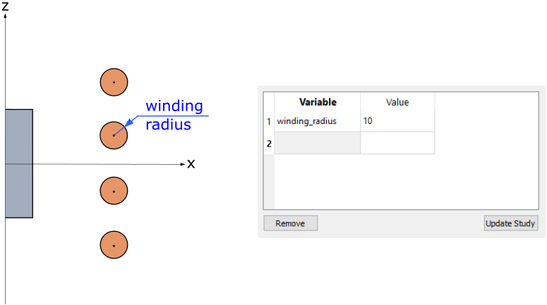
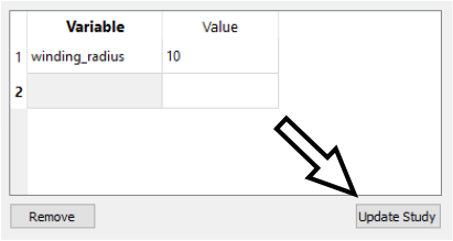
In the NoteBook window enter the names and values of the variables you are going to use in your model. In this example we will create a variable named winding_radius and assign a specific value to it.
2. Implement variables in geometry
Variables are implemented in the geometry by using them to define parameters connected with primitive shape creation, translation operations and other geometry creation/modification actions.
If we want to define the coil winding diameter, we must first think of how to create the windings. The easiest way is to create a base circle for the upper winding and then use Multi-Translation tool to create the rest.
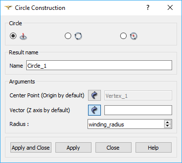
Because the circle size in circle construction tool is defined through radius, we can implement the diameter variable through radius size in the creation of the upper winding base circle. To do that, create the circle using Circle Construction tool, but in the Radius box do not write a specific number, but rather the name of the variable we created earlier - winding_radius.
IMPORTANT: To efficiently implement the variables into geometry, you must first understand how to create the specific geometrical aspect of the model and where the variable of interest will be used.
3. Change the geometry
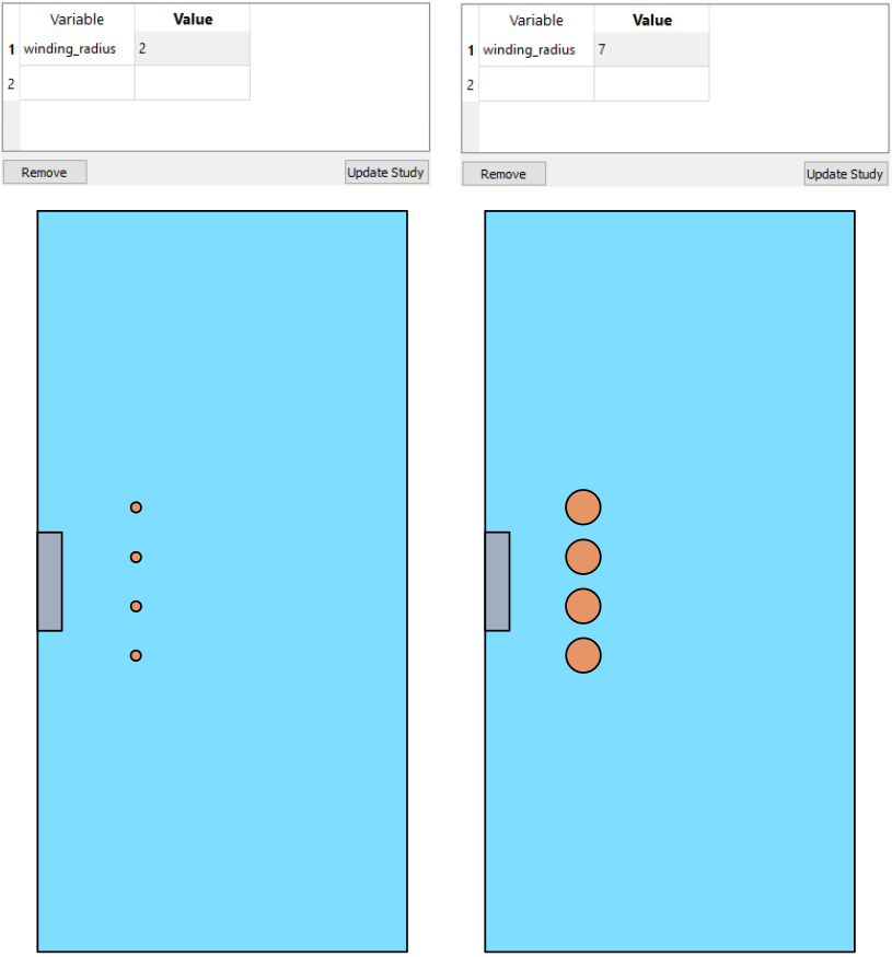
When the rest of the model has been created and partitioned, you can go back to the NoteBook and change the parameter specified before. After changing the value, click Update Study and evaluate the new geometry.
After Update Study the parameterised geometry as well as the geometry and mesh built from it will change.
IMPORTANT: After the change of parameters and study update, you need to switch to Mesh module and export the new mesh to CENOS before recalculating the simulation!
Limitations
Although an effective way to quickly change the geometry, there are still a number of things to keep in mind when creating a parametric model.
Parametric number of objects
While making sizes and distances in your model parametric will allow you to modify your geometry with only a few actions, other parameters can take longer to change.
IMPORTANT: The change of parameters that define a number of objects, not their size, will require a new group and a new mesh for every modification.
For example, if you create a parameter for the number of windings, it will essentially change the number of objects in your Partition every time you change it. It means that it will create conflicts in the old groups, so you will have to recreate the groups every time you change the number of windings.
Although mesh will re-compute itself, you will still need to spend additional time to make sure that everything with groups and mesh is correctly defined/created.
Geometry overlapping
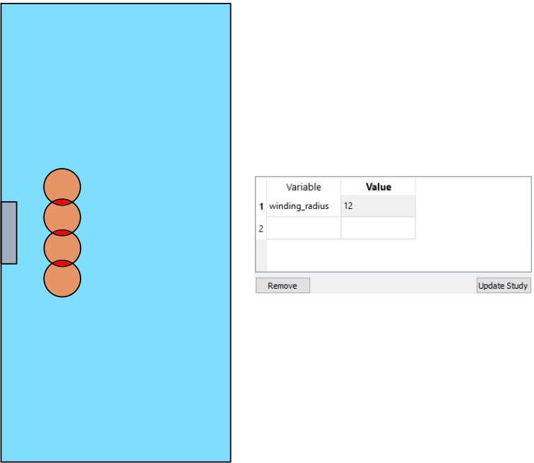
By changing parameter values, the geometry can be made unphysical, i.e. domains such as workpiece and coil or coil windings themselves can overlap each other - avoid these situations and always check the geometry after every study update!
In the example of coil winding diameter parameterization, if the winding_radius is defined as bigger than 10, the windings will overlap each other.
This in turn can cause problems in meshing and simulation calculation, as it is not physically correct.